|
| |
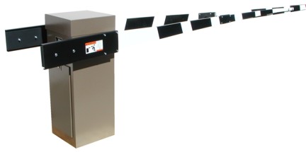
INDUSTRIAL BARRIER GATE
Model 350 (18, 20 & 22 Foot Arms)
Provides access control wherever it is necessary
to check entering or exiting vehicles for identification or inspection. The gates may be
controlled from stations directly adjacent to gate location or from remote areas. Ideally
suited for military bases, nuclear power plants, shipyards, airport
freight depots, industry, munitions plants, mines, etc.
SPECIAL
APPLICATIONS ONLY - CALL FACTORY FOR DETAILS |
FEATURES:
100% Solid State Plug-in control
circuit.
Theft and tamper resistant, no exterior mounting
bolts.
Different gate arm lengths. Three models are
standard, other lengths are available, depending on the width of your roadway.
Heavy duty mechanism. A heavy duty, long life
reduction mechanism provides the drive from the motor to the gate arm shaft.
Rugged, weatherproof, 10-gauge steel housing.
|
TWO 301 GATES:
Where very heavy traffic requires greater speed
than provided by the 350 gate, two Model 301 gates can be used on opposite sides of the
driveway. Consult the factory for details. |
|
HOUSING:
The housing shall be weatherproof and
constructed of ten (10) gauge cold rolled steel. All seams, joints and supports shall be
electric bead welded. (Spot weld is not acceptable for the housing construction).
Access to the interior of the housing shall be
provided by a key locked door. The door and the top lid shall be designed to retard
against unauthorized entry, tampering and vandalism. An opening for conduit stub-ups shall
be provided at the base of the unit.
The cabinet shall be finished with two (2) coats of
primer, followed by two (2) coats of baked enamel to insure lasting beauty and protection.
MECHANICAL:
The gate arm shall be driven by a
1/2 horse
power, 115 VAC single phase instant reversing motor. The motor shall be connected by a
V-belt to a heavy duty, 60:1 ratio, single reduction speed reducer. The output shafts
shall be connected by #50 chain and sprockets.
The motor shall not draw more than 15 amp surge
current at 115 VAC. Adjustable cams shall be provided to allow for proper adjustment of
gate arm travel. |
CONTROL CIRCUITRY:
All control circuitry, logic, motor
starting, etc., shall be contained in one (1) easily removable, semi-sealed, housing
(hereafter referred to as the control logic assembly). All connections to the control
circuitry compartment shall be made by plug-in connectors.
One (1) standard control logic assembly shall be
capable of providing all system logic as well as manual functions and shall be of solid
state design. No relays or contactors shall be accepted in this unit.
Operational mode changes shall be accomplished by
dip switches located on the control board. No circuitry modification, addition or deletion
shall be required to accomplish standard mode variations.
ELECTRICAL CHARACTERISTICS:
Phase input shall be fed through a series
trip magnetic circuit breaker of UL approved type. This circuit breaker shall disconnect
all cabinet power as well as offering electrical overload protection in the gear motor
circuit and primary cabinet power circuits. |
 SPECIFICATIONS
350
LITERATURE SPECIFICATIONS
350
LITERATURE

 |